Project Inspiration
When I finished my Bachelor’s I wanted to make my way into the area of embedded systems and firmware development and I figured this would be a good way to prove I had a bit of skill and could learn quickly. I had seen a few similar projects and wanted to make my attempt. Going into the project I had experience with engineering small projects, but never anything that went out of the initial prototype stages. I wanted this to be a good example of what I already knew, but also an opportunity to strengthen and grow my knowledge. What would serve this purpose would be dubbed: The Survival PCB Business Card.
The TL;DR
- Board designed in KiCad, PCB thickness of 0.6mm(Allows flex for battery), gold ENIG finish(to prevent solder bridging on fine pitch components)
- ATmega168PB microcontroller
- Code written with Atmel Studio in embedded C
- Flashed using AVR Pocket Programmer(Sparkfun) on 6 pin ISP pad(right side of board)
- VEML6070 UV sensor and LSM303AGR accelerometer/magnetometer on I2C bus
- LEDs arranged in a circle and charlieplexed
- Tap to change mode
- Compass mode lights up LED closest to north
- Temperature mode lights up LED corresponding to temp in Fahrenheit
- UV mode lights up LED corresponding to the UV index
- Hidden game mode to stop LED at designated spot (similar to cyclone arcade game, but without the scam)
The Longer Story
Initial Concept
While I had written some code before and cobbled together circuits, there was a lot I didn’t know before starting this project. I had never written a driver from scratch, never designed a PCB, never worried about part obsolescence, and so on. So I spent a bit of time browsing sensor breakout boards on Adafruit for inspiration and settled on my initial concept.
At the beginning I decided I wanted to use an AVR microcontroller(ATmega168PB) connected to a UV sensor(VEML6070) and accelerometer(LSM303DLHC). I would design the circuit to fit in a business card form factor and would offer the user the ability to switch between a few modes via a button. To convey the information in a useful way, I decided to use the silkscreen of the PCB along with LEDs arranged in a circle to show what sensor was currently active and what the value was. I also wanted to power the card from a CR2032 coin cell battery to keep a lower profile. For software, I wanted to avoid Arduino and write my own drivers and firmware from scratch.
This was my starting point for the project, so I ordered development boards for the micro and the two sensors. I had parts for the rest that would do while I got some initial prototyping done.
Learning The Hard Way
My initial circuit design on a breadboard and writing some software wasn’t too difficult as it was a task I had performed before. But what followed was full of bodge wires, board redesigns, and valuable learning experiences.
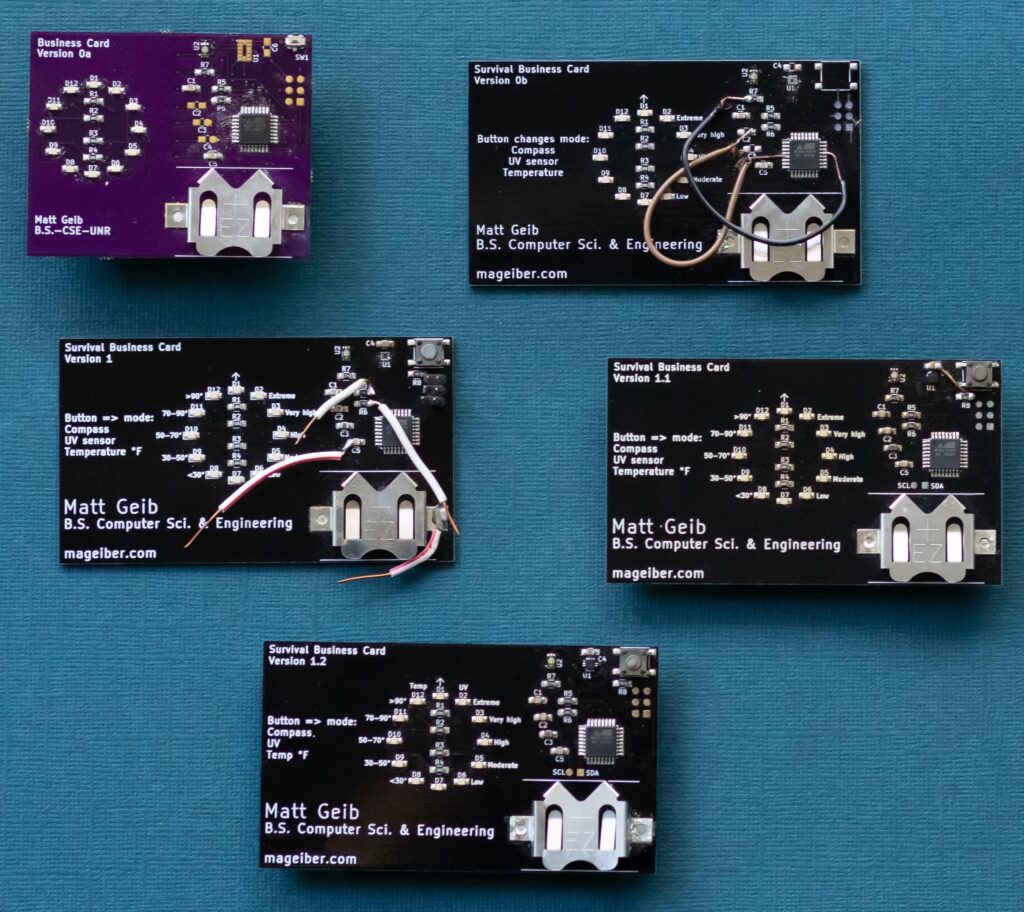
Survival PCB Business Card Version 0a
The first design was on a smaller board so that it wouldn’t cost as much through OSH Park. I knew it would require redesign later, but wanted the PCB soon to get a feel for the real hardware. It also featured a much smaller switch which turned out to be unusable. This was also about the time that the LSM303DLHC part I was using went end of life.
Survival PCB Business Card Version 0b
Board Version 0b swapped out the LSM303DLCH for a newer version of the chip, the LSM303AGR. It also swapped out the 90 degree angle small tactile button for a more standard button. The board itself was full size, but did end up having some minor wiring issues as well as using HASL Lead free as the finish(to save some money), which plagued the fine pitch LSM303 chip for a few revisions. It should be noted here that the soldering was done via a modified reflow oven(the famed T962 mod) and by hand, so the finer pitch components definitely suffered.
Survival PCB Business Card Version 1.x
The next version I deemed Version 1, where most things were ironed out and I could begin refining the software to work well and meet my requirements. I had a few I2C protocol issues that I was able to iron out using a Digilent Analog Discovery and other small developments in regard to putting everything to sleep to conserve the small battery it used. Version 1.1 wired up a few other features of the magnetometer chip and added dedicated pads for SCL and SDA for I2C. Version 1.2 switched to using Gold ENIG, which solved the issues I was having with reliability of connections when reflowing. This was the final version I would give out to prospective employers at onsite interviews after college. I like to think it gave me an edge and helped me land my first job in the field.
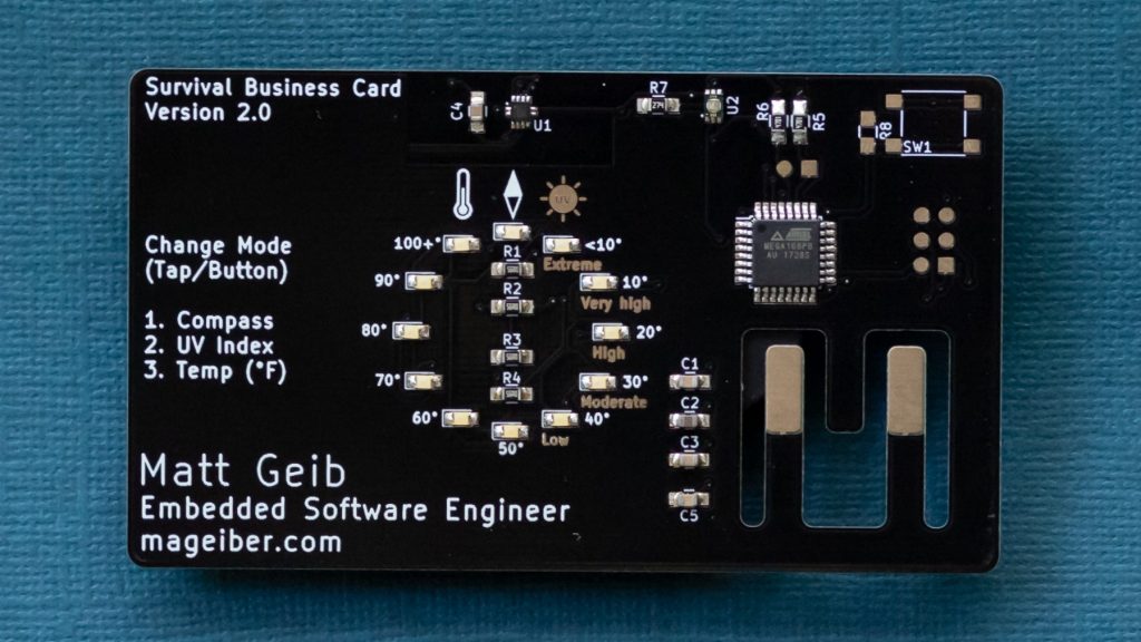
Improvements and Current Version
I revisited the board after gaining a bit of real work experience in embedded systems. My primary goals were to cost reduce and give a better user experience. To cost reduce, I minimized the parts needed. Why use a switch, when the accelerometer has a click function(read as: do it in software!)? How about embed the battery in the board and remove the holder? This allowed and required the final product to be much thinner. The board itself had to be made thinner to allow enough flex for the battery to be wedged in it. As final touches I updated the text, rounded the corners, and made a few software tweaks. This is the card as it currently sits. The VEML6070 has since been marked as end of life, right after I was content with the hardware. But that’s how it goes.
Future
Further hardware improvements could be to add voltage protection/regulation and hook up a dedicated crystal(as opposed to using the internal oscillator). However these would also come at adding to the cost I just lowered. The voltage protection/regulation for when a user gets creative with the battery/power source. The dedicated crystal would allow for adding timer/clock feature. This could in theory be done with the internal oscillator, but over time wouldn’t be as accurate. As far as software, it would benefit from a calibration routine for the magnetometer. It’s usually pretty close without it, but better accuracy could be achieved. Lastly, I would make the software a bit more robust to errors that could occur on the I2C communication. I haven’t experienced issue, but acknowledge that there are potential issues there.